Homepage > Crank Shafts

The crank shaft needs to be magnetized in two directions perpendicular to each other. A circular magnetic field is used to detect longitudinal flaws in the part.
A circular magnetic field is generated by passing a current through the length of the crank shaft.
Calculation of headshot current is done as per the formula given in ASTM standards.
Head Shot Current = 20 X Diameter(mm)
In the above formula, the diameter should be taken as double the diameter of the lobe.In order to detect transverse flaws, we need a longitudinal magnetic field, which is generated by using one or more encircling coils.
As per ASTM standards, the length of the crankshaft magnetized by the coil is equal to the inside diameter of the coil.
To cover the entire length of the crank shaft, the coil must be moved to different points along the length of the crank shaft, separated by 90% of the coil diameter. This will ensure the 10% overlap specified in the ASTM standards.
Formula for calculation of coil current

Also, in the above formula for the current requirement for coil shot, while calculating the L/D ratio, L must be equal to the inside diameter of the coil & not equal to the overall length of the crank shaft.
In the above formula, the diameter should be taken as the diameter of the journal.
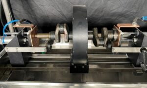
A bench-type machine is used to perform magnetic particle testing on crank shafts. The crank shaft is placed on the steady rollers fitted on the head & tailstock of the machine. A pneumatically operated arrangement is used to clamp the crank shaft from both ends. Pneumatic clamping ensures that there is no sparking when a high current is passed through the crank shaft. The use of braided copper pads is also recommended to eliminate arcing sparks.
Conventional Technique
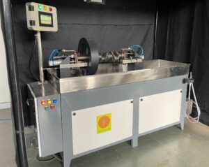
A two-vector PLC-based bench-type magnetic crack detector machine is used to perform testing on the crank shafts
Testing Procedure for conventional machines
- Clean up & dry the crank shaft’s surface before inspecting.
- The crank shaftis placed on the steady rollers.
- Now apply magnetic solution bath to the crank shaft.
- Press the ‘Cycle Start’ button.
- The crank shaft automatically gets clamped.
- Stop the flow of bath.
- Now, the current passes through the crank shaft.
- It shows up on the digital metering unit.
- The crank shaft automatically gets de-clamped.
- Inspect the crank shaft under UV light for longitudinal defects. Rotate on steady rollers.
- Move the coil to its 1st position
- Now, again apply bath to the job.
- Press the ‘Cycle Start’ button.
- Stop the flow of bath.
- Now the current passes through the coil.
- It shows up on the digital metering unit.
- Inspect the crank shaft under UV light for transverse defects. Rotate on Rollers
- Move the coil to next position & repeat the above 6 steps.
- Demagnetize
Multidirectional Technique
In this tailor-made machine, two coils are used. The coils are automatically moved using pneumatic actuators. The automatic movement of coils facilitates the loading of part on the machine. Each coil covers a length of 450mm from each end of the crank shaft. So, two coils cover an area of 900mm. Crank shafts upto 900mm length can be checked on this machine.
Testing Procedure for Multidirectional machines
- Clean up & dry the crank shaft’s surface before inspection
- Place the crank shaft on the steady rollers.
- Now apply a bath to the crank shaft.
- Press the ‘Cycle Start’ button.
- The crank shaft will automatically get clamped & Coils will come into position
- Stop the flow of the bath.
- Now the current will pass through the crank shaft& the coils in multidirectional mode.
- It will show up on the digital metering unit.
- The crank shaft will automatically get de-clamped.
- Inspect the crank shaft under UV light for defects in all directions. Rotate on rollers.
- Demagnetize
suitable products
Standard MPI Machines
Engineered for precision and efficiency, the Standard Bench Type Magnetic Particle Testing Machine is suitable for entry level testing.
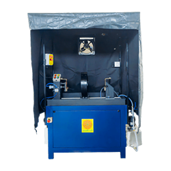
PLC Controlled MPI Bench
With PLC Controlled bench type Magnetic Particle Inspection Machine, you can accurately control the process parameters for reilable results.

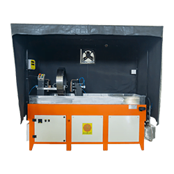
Multidirectional MPI Bench
The ultimate solution for robust non-destructive testing, this machine offers multi-directional magnetization for inspection in all directions in one shot..

Demagnetizers
Demagnetizers stand as a key tool in maintaining excellence in production, with the flexibility to handle different materials and magnetism levels, coupled with energy-efficient and user-friendly design.

DIVE DEEPER: GET YOUR HANDS ON OUR PRODUCT BROCHURE!
Explore More, Discover Better!
- In-Depth Details
- Product Insights
- Expert Recommendations
Download Our Brochure Now!